Closed-Loop Stepper Driver
10-12-2018
When designing the control system for my portable CNC machine, I found that none of the control systems on the market really satisfied all of my requirements. As my machine is modular and uses 2 motors to drive each axis in opposite directions, most GRBL-based motion controllers would not work with my setup. Moreover, as I intend to do quite heavy machining and do not want each pair of motors to ever go out of sync with one another, I wanted my control system to be closed-loop (i.e. incorporate positional feedback). Now, there are plenty of closed-loop CNC controllers out there, however they are all rather expensive and quite bulky, making them less than ideal for a portable machine. The systems are also not very expandable. Taking all of this into account, I decided to design my own controller!
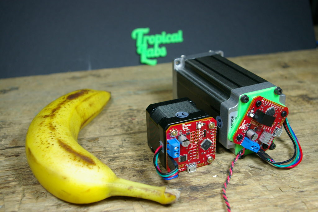
The most expensive components of a closed-loop system are the encoders themselves. High-resolution optical encoders are typically £20+ and are very sensitive to dust ingress. When used in industrial servos, they are typically enclosed inside a NEMA-style enclosure - which pushes up the price considerably. However, a Kickstarter project caught my eye which uses a different means of feedback. The Mechaduino, pictured above, uses a magnetic encoder: they work on the GMR (Giant-Magneto-Resistance) principle, and use a magnet that is diametrically magnetised, attached to the motor shaft. Inside the magnetic encoder, there are 2 GMR sensors at 90° to one another, and by looking at the magnitude of the magnetic field in both directions, you can use a bit of trigonometryto work out the orientation of the magnet.
The other nice thing about these encoders is that at £3.50, they are far cheaper than their optical counterparts!
I began designing my own closed-loop stepper driver, based closely on the Mechaduino, however they were some key differences, some favourable, some that in hindsight were a very bad idea. The first change I made was to the control interface. The original Mechaduino has step/direction pins for use with regular open-loop controllers, but to get positional feedback back from the motor you needed a USB-serial connection. With 5+ motors, USB-based communication is somewhat impractical. I also wanted to put as much of the “real-time” processing on the motor board as possible. I live next to an industrial estate, so I have become accustomed to electrical noise causing spurious signals in my electrical circuits. I had heard horror stories of CNCs losing steps and ruining parts due to interference on the driver’s Step and Direction lines. Initially I toyed with the idea of streaming G-code to each motor, so I incorporated an ATMega328p to act as a co-processor running GRBL. However, as you will find later, this has its problems…
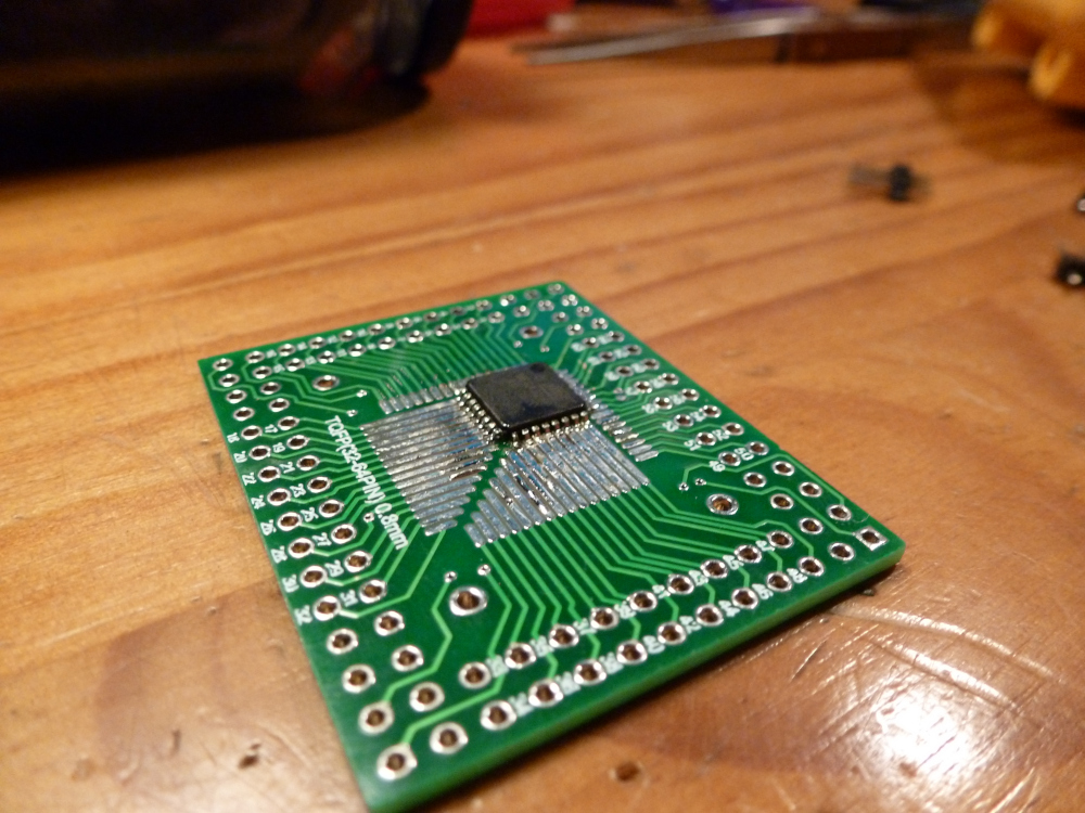
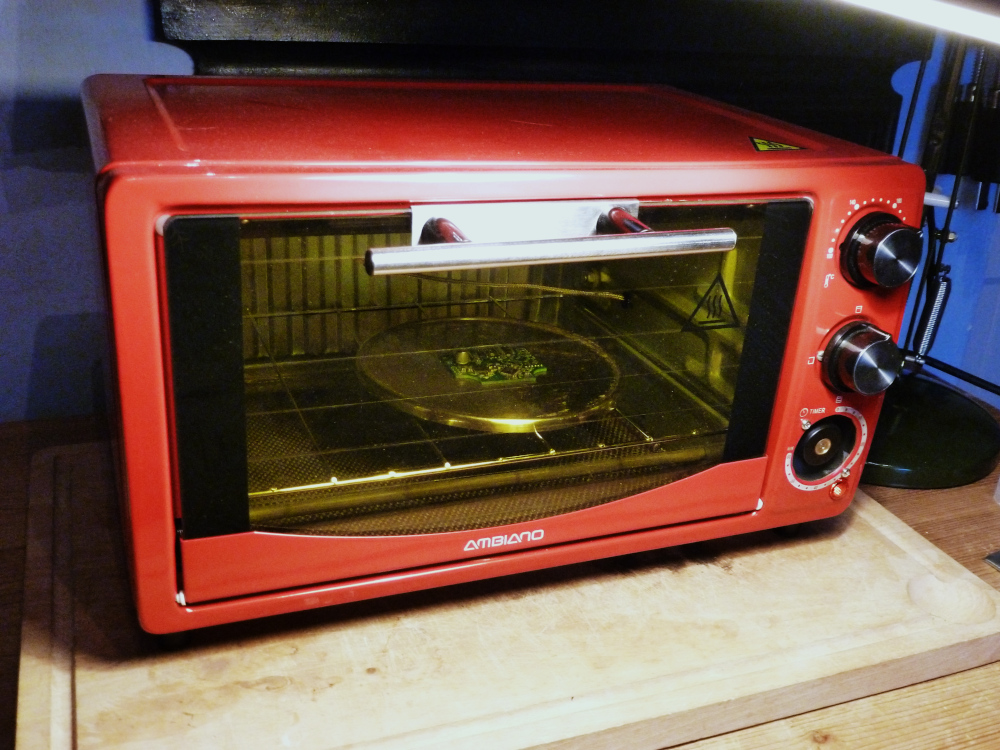
Before dealing with this probelm, however, I had to learn how to solder components of this size. I did some preliminary tests with a handheld iron and some Atmel microcontrollers and found that I could get decent joints on TQFP-48 chips, but I could not reliably solder the QFN-36 motor driver that I needed for this project. I’m sure with practice I could solder these chips by hand reliably if I had to, but my PCB design is quite crowded, so I decided to reflow these boards. As this was the first project that had required reflowing, I made an oven specially, the article for which can be found here.
As it turned out, the reflow oven project was far more successful than the project I built it for, as will become apparent…
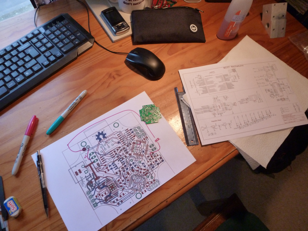
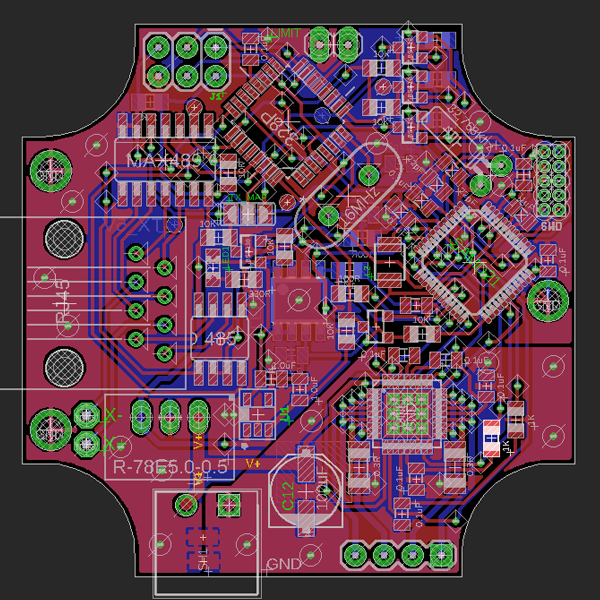
As is always the case with electronics projects, I found major problems in my design after ordering the PCBs, so I spent a lot of time manually re-routing my PCBs with a stanley knife and flying wires (see above). The first design flaw was the idea of running GRBL as a co-processor directly on the motor driver boards. For a single motor, this system works fine, but when trying to co-ordinate multiple motors, the issue of synchronisation arises. While GRBL is effectively a real-time control system, the time between a command being sent and that command being executed is not constant. This is because the G-code commands are held in a serial buffer until GRBL can execute them, so once you are running an instance of GRBL for each axis, it is hard to guarantee that the axes will all move in sync with one another. I had planned to deal with this by having a synchronisation pulse that set a flag in GRBL allowing the next line of G-code to be executed. However, my initial tests of this scheme were disappointing and unreliable.
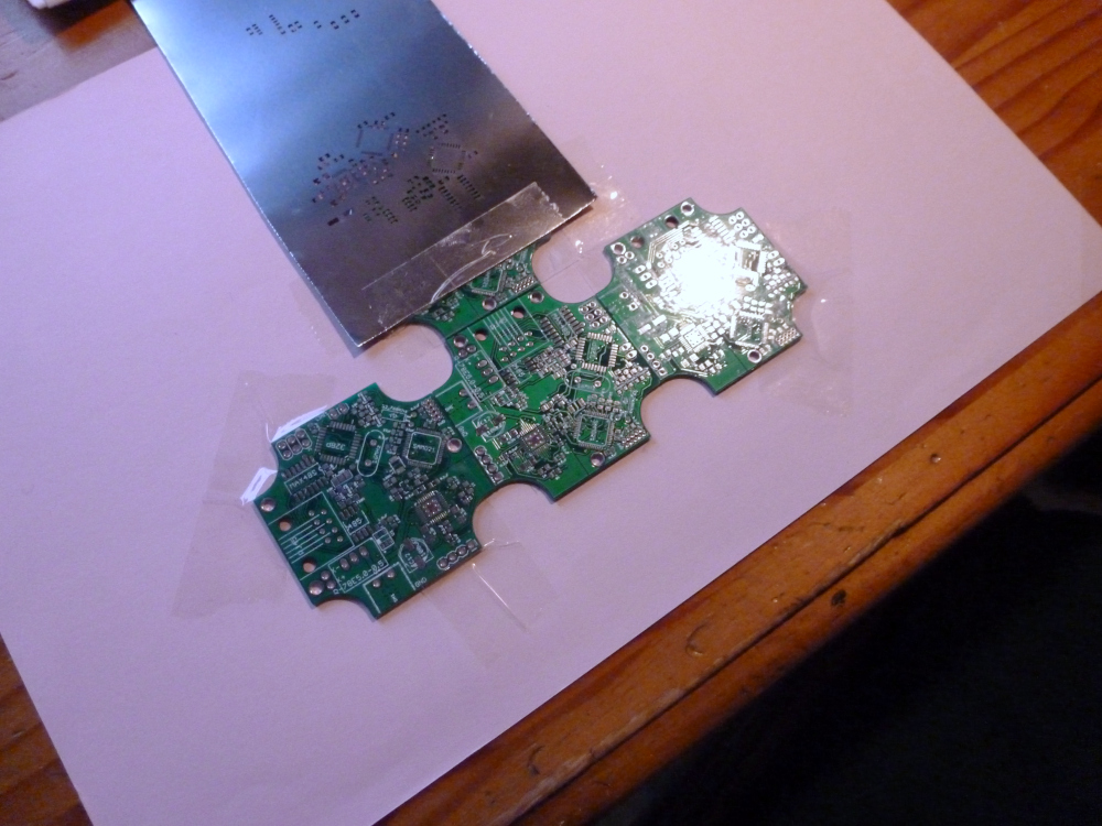
The next major problem was communication. I designed each motor controller with full-duplex RS485 over twisted-pair ethernet cables, with the intention of sending all motor controllers G-code as serial strings, then multiplexing throughthe receive lines to record the returned co-ordinates. The fact that the motors can transmit a message without being polled by the master means that I would need some sort of FIFO buffer, and would have to switch through the motor channels fast enough to receive any error/emergency stop messages. Half-way through designing the master controller, after looking at the BOM, I have decided that my approach was not particularly efficient or scalable. Unfortunately, by the time I had decided to completely redesign my motor controller, most of the I components I needed had arrived! Determined not to waste the time and money I had put into the design so far, I decided to use these boards to hone my solder reflowing skills…
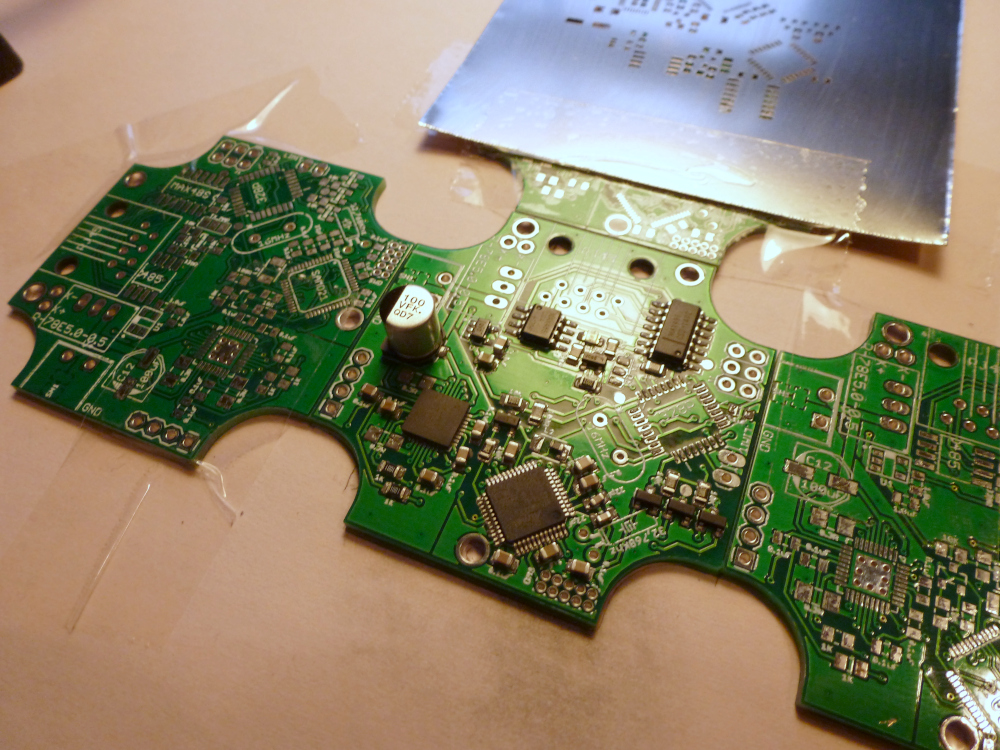
When I ordered my PCBs, I had the option to add a laser-cut solder stencil for a fiver (I’m sure at this point, if you have seen any electronics vidos on YouTube, you can probably guess where I get my PCBs from). This meant I did not have to worry about manual paste dispensing, though I did have to experiment a bit with the consistency of the paste. Tempting though it may be, a DIY pick and place machine is not on the cards right now. I placed all of the components manually, then began trying different reflow curves. The final results were impressive as far as the soldering was concerned, if a little lacking when it came to function. I have put this project on the back-burner for a while, but I do have a plan for a version 0.2 of this project. Some of the work I am doing currently involves running PTP clients on small microcontrollers. PTP is a network synchronisation protocol, and one idea I have for continuing this project is to distribute timestamped G-code over Ethernet, then program the motor controllers to execute the instructions based on their network-synchronised clock. However, this is still a long way off, and if nothing else this documentation of an otherwise failed project may help you avoid the same pitfalls that I fell into!