Reflow Oven
10-04-2018
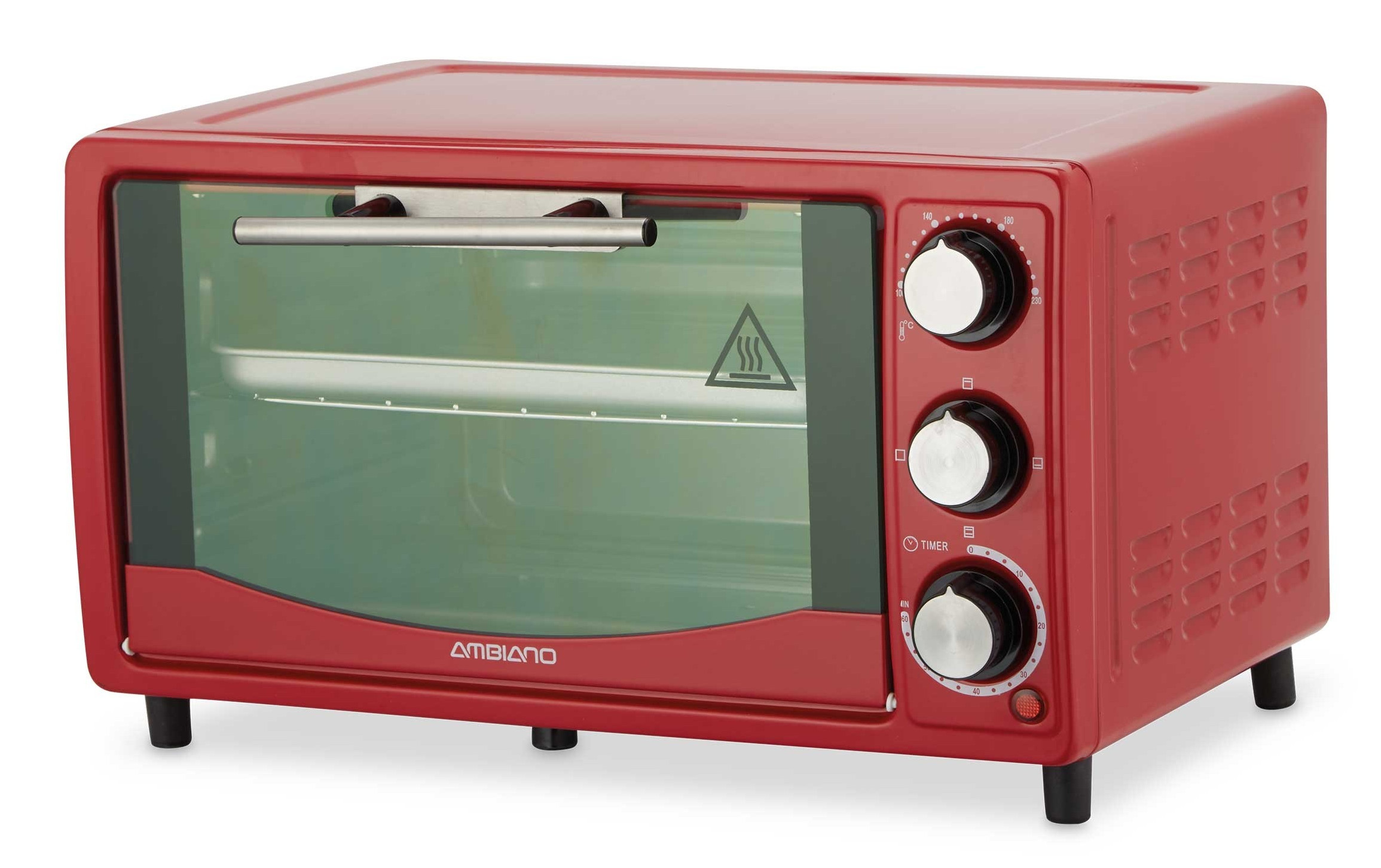
Recently, many of my electronics projects have required the use of components that are only available in SMD form. While I can solder most SMD components by hand, and most components can be bought on break-out boards, I decided that it was time to up my game in the SMD soldering department. After all, SMD is not going away, and I want to be prepared for when and if the through-hole components I need become completely unavailable. The ‘breaking point’ for me was during the development of my closed-loop stepper driver, where I had to use a fine-pitched QFN chip for the motor drive, and was destroying several chips trying to solder them by hand. To prevent further frustration, I decided to make a reflow oven. There are plenty of articles online showing toaster -> reflow oven conversions, however they all tend to be overly complex and tend to be optimised towards buying the components as a kit rather than using the dev boards we already have on hand. Moreover, they tend to be designed as ‘add-on’ controllers that are housed outside of the toaster oven enclosure, making them bulky and less pretty (I know looks aren’t a priority here, but it’s always nice to have decent looking tools). After looking at some open-source controllers online and not being particularly happy with any of them, I decided to make my own. For the oven I used the cheapest one I could find: the ‘Ambiano Mini toaster oven’ from ALDI. These ovens only cost £20 new, but are surprisingly well made. Most importantly, they have lots of internal space to house a new controller!
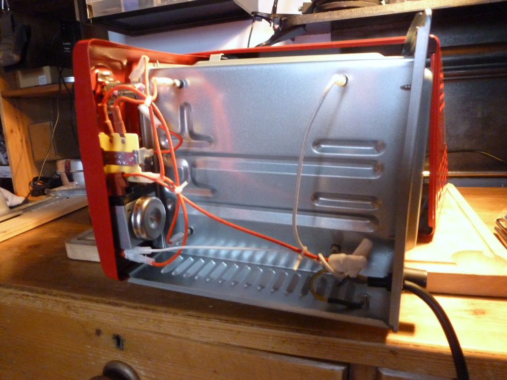
The most important aspect of a reflow oven in my opinion is the ability to ramp up the temperature as rapidly as possible. To do this with an oven that is relatively underpowered, I had to insulate the oven as well as possible. For this I used ceramic pizza oven insulation, sandwiched between the inner and outer shell. One thing to note when working with this insulation is that it is made up of lots of loose fibres. When working with it, breathing protection must be worn, and work outside to avoid dropping fibres everywhere. To neaten up my insulation, I enclosed the ceramic fibre in an aluminium foil blanket, then covered most of the foil with kapton tape, creating a removable blanket with cutouts for the heating elements. A quick look inside the enclosure (pictured below) reassured me that I would have plenty of space to install the controller. I also suspected I would be able to re-use the existing dials on the oven to interface with the controlller, meaning I wouldn’t have to drill any more ugly holes in the outer enclosure. I stripped out most of the innards straight away, but kept hold of the wires and spade connectors. The original ones are fibreglass high temperature cables, so it seemed sensible to re-use them when wiring in my controller.
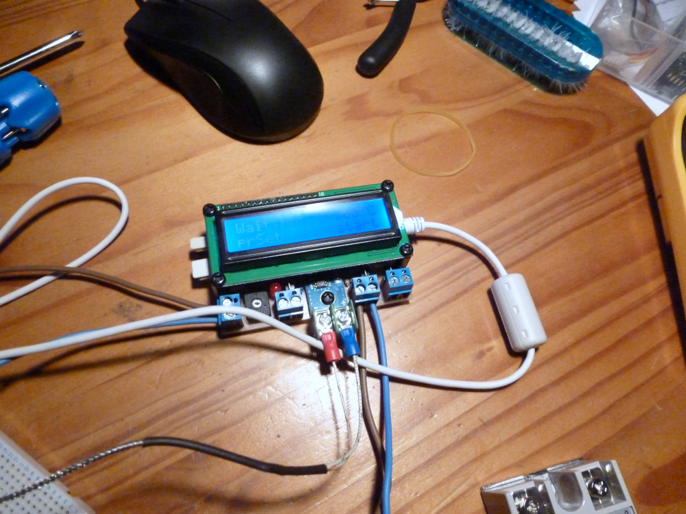
While my controller is not stock, I did not build the entire PID control system from scratch. My firmware is based very closedly on giacu92’s reflow oven firmware for the Arduino Nano. My version is very similar, but I have changed the menu structure and interface connections to make it more suitable for my oven’s existing controls. One very nice feature of giacu92’s firmware is that it is designed to be paired with a control/tuning application, which means I don’t need to make a detailed means of tuning the PID and reflow curves through the oven controls. Other than a few firmware adjustments, my main changes to giacu92’s project were to the hardware layout. Because I wanted to build the entire controller into the oven housing, I modified the PCB design to fit within the footprint of the LCD screen, and made the layout entirely through hole and single-sided. It is worth noting that the control circuit is simple enough to make on stripboard or even just soldered point-to-point, but as I have the equipment to etch simple single-sided boards on hand, this just neatened everything up. The PCB design is also optimised for keeping the oven heat away from the control circuitry. This probably isn’t necessay, as the control cavity is insulated and fan cooled, however I didn’t want to take any chances!
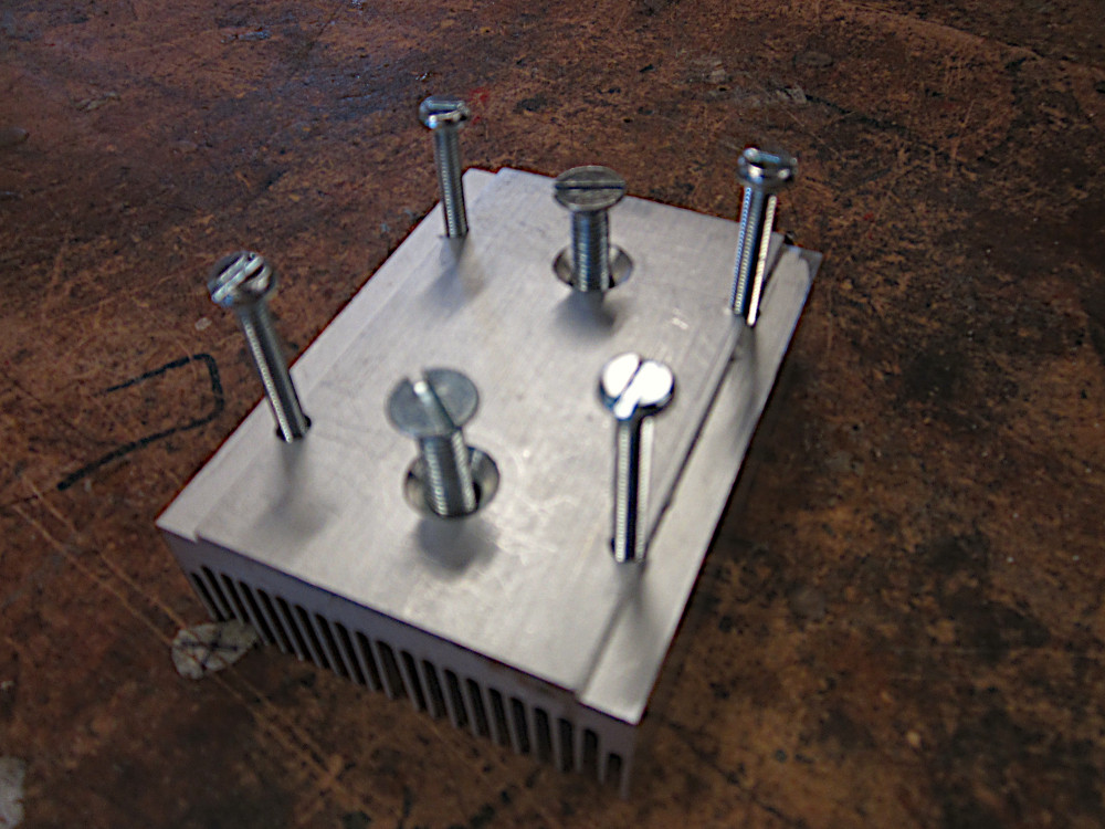
To actually control the oven I am using two Solid State Relays, which independently control the top and bottom set of heating elements. This gives me some control over temperature distribution in the oven, and I have configured the controller to drive the bottom elements slightly hotter than the top elements, to prevent overheating of electronic components when reflowing. It is worth noting that in this oven, there are 4 heating elements, but they are rated at 120V, so must be wired in series pairs. To help with temperature distribution I also added a shrouded fan inlet which circulates air to avoid uneven reflowing. This fan also helps ramp the temperature down after the peak reflow temperature has been reached. The SSRs I am using are generic ‘Fotek’ models from EBay. As a word of warning, virtually all the ‘Fotek’ SSRs on EBay are fakes. They still work just fine, but I would not take them anywhere near their 25A rating. As the ALDI toaster oven is rated at 1200W@230VAC, and I am switching the top and bottom elements separately, the peak current in the SSRs won’t exceed 3A. Nevertheless, I didn’t want to take any chances, so milled down an old PC heatsink to mount the relays to (see picture below), and oriented the heatsink so that there will be a constant flow of forced air over the relay block. Admittedly, my desire to have the controller entirely enclosed within the oven made me much more nervous about the possibility of thermal runaway.
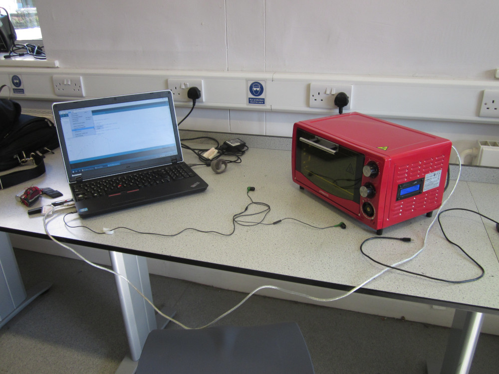
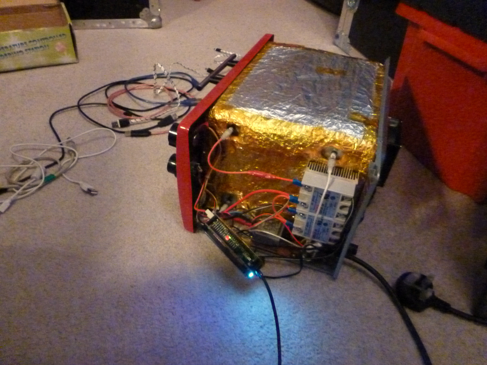
After mounting the solid-state relays it was simply a case of adding the insulation blanket, silicon-sealing all the joints between the sheet metal parts, and adding a hole for the thermocouple. I tried to do the wiring all by the book, with proper spade terminals, star grounding, and nylon stand-offs for all the low-voltage circuitry. I also replaced one of the dials with a cutout for a small 40mm fan, to keep all the control circuitry cool. The tricky bit was getting everything to sit nicely while I positioned the outer shell! Now while the build quality of the original ALDI oven is not bad, I don’t want to be taking it apart too often to reprogram the controller, so I added a USB port to the back, allowing me to tweak the PID controller and re-write the firmware while the machine was running. This is also much safer than testing the unit with all the mains wiring completely exposed. I do not endorse testing a reflow oven on a carpet with live contacts hanging out, but suffice to say I only did this once to make sure it was working before re-assembling it :)
I have published all the firmware, schematics, PCBs and BOM to GitHub. This is far from the most complete reflow oven design, and I highly reccomend you check out both giacu92 and 0xPIT’s reflow oven controller for further information if you are planning to design your own. A reflow oven is a very handy thing to have around, and building it was great fun. Hopefully some of the information here is helpful for if you build your own. As for the firmware, I am making small adjustments and bugfixes as I find them, but I will not be actively maintaining this project on Github. If you have any firmware enhancements, be sure to contribute them back to giacu92’s repository - as far as I can tell it is still being actively maintained.