Pickup Winder
20-06-2016
For a while I have wanted to try making my own guitar pickups, but always thought it would be too expensive to get started. Sites like Stewart Macdonald sell pre-built pickup winders, but they are eye-wateringly expensive! Lots of people online have shown it’s possible to wind pickups consistently with nothing more than a metal rod and a hand-drill, but this felt a little too crude for my liking. Consequently, I decided to build my own custom pickup winder.
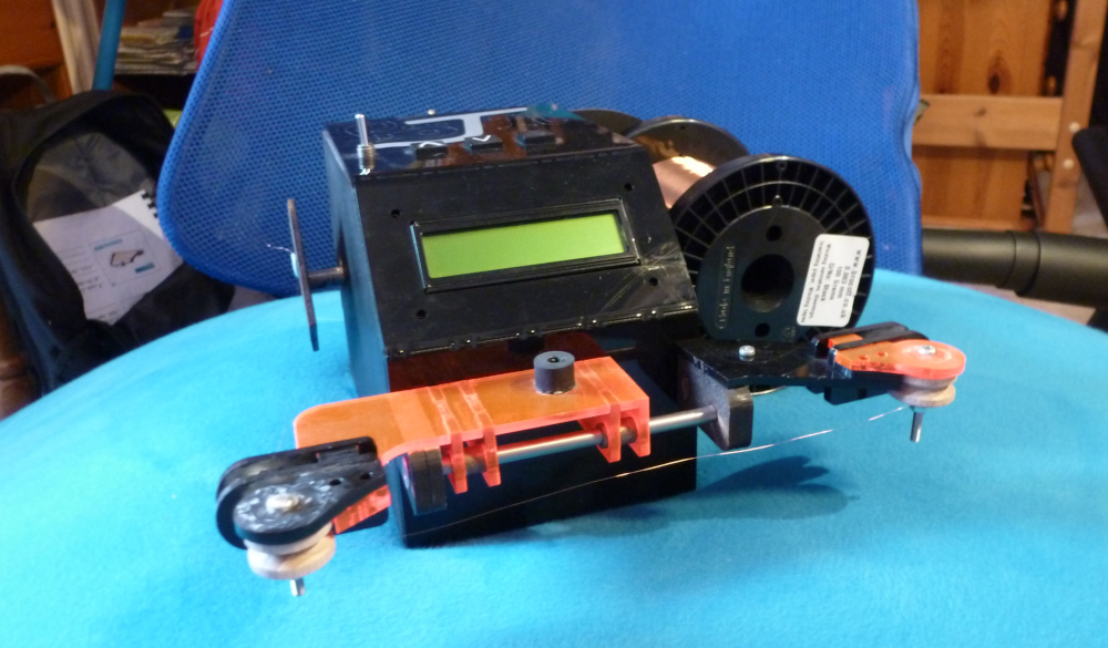
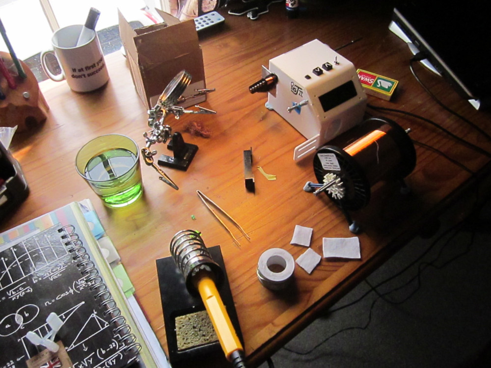
In fact I ended up building two pickup winders: the white one pictured below was Version 1, and thanks to poor research on my part, had a variety of design flaws. The machine was usable, but it was clunky and a pain to use. Version 2 (the black and red machine pictured at the bottom of this page) built upon the design of version 1, but corrected many of the original winder’s design flaws.
Version 1 was relatively simple: the main enclosure housed a DC motor that drove a shaft that mounted the pickup bobbin. It has been a long time since I saw version 1 (it was dismantled long ago as an organ donor for Version 2) however I seem to recall that in my 14-year old wisdom I didn’t even use bearings for the drive shaft! I also designed a ridiculous cam-based oscillator mechanism into the casing to distribute the coil windings automatically, but thankfully decided against actually implementing it. The only major feature of Version 1 which I kept on was the control system. This essentially consists of an Arduino Nano, an LCD, some push-switches, an opto-reflector sensor and a MOSFET to switch the motor. All the circuit does is keep count of the number of rotations the bobbin has turned through, by triggering the opto-reflector off the edge of a black and white strip on the drive shaft. It worked reasonably well in the first pickup winder, so there was no real need to replace it.
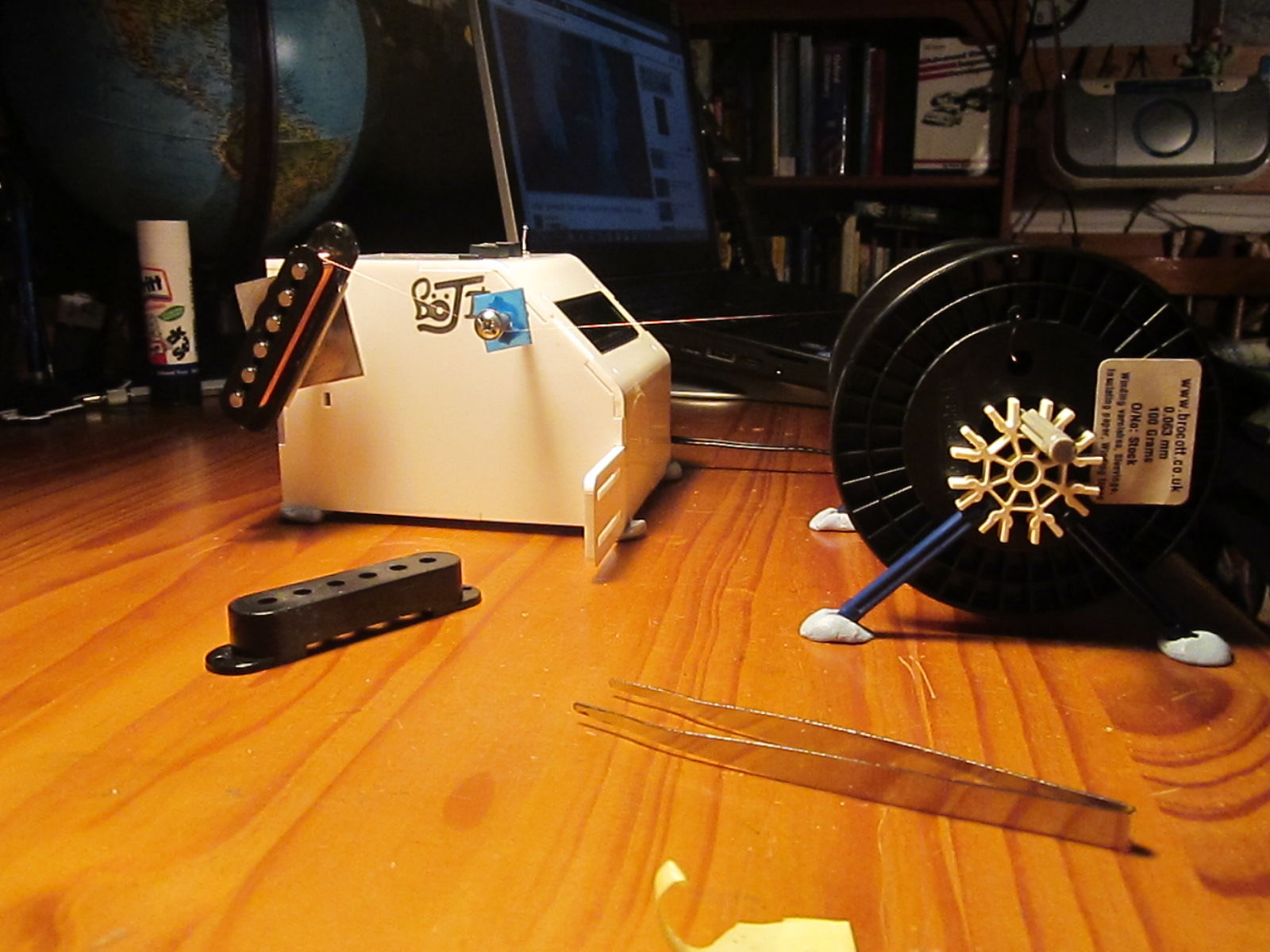
The main problem with the first pickup winder can be seen in the picture above. You can see that I had the wire spool on a makeshift stand, with the thin wire being drawn off the spool tangentially. While this may seem normal, it is not how most pickup winders operate. This is because the wire in question is very thin (approx 0.06mm across!), so having to pull the heavy spool around puts excessive tension in the wire. I found that whenever I stopped the machine, the spool would not keep on spinning, and its inertia was enough to snap the pickup wire and force me to start winding from scratch. This resulted in a lot of waste copper wire, not to mention increasing frustration! It turns out that the “proper” way of removing wire from the spool is to pull it off axially, as illustrated at the bottom of this page. This is a far superior solution, as it does not require the spool to move at all while winding the pickup. The low thickness of the wire makes the extra ‘twist’ of the wire with each rotation as it is pulled off the spool unproblematic, and the tension in the wire can be as low as desired. Armed with this new knowledge, I decided to go back to the drawing board and design pickup winder MkII…

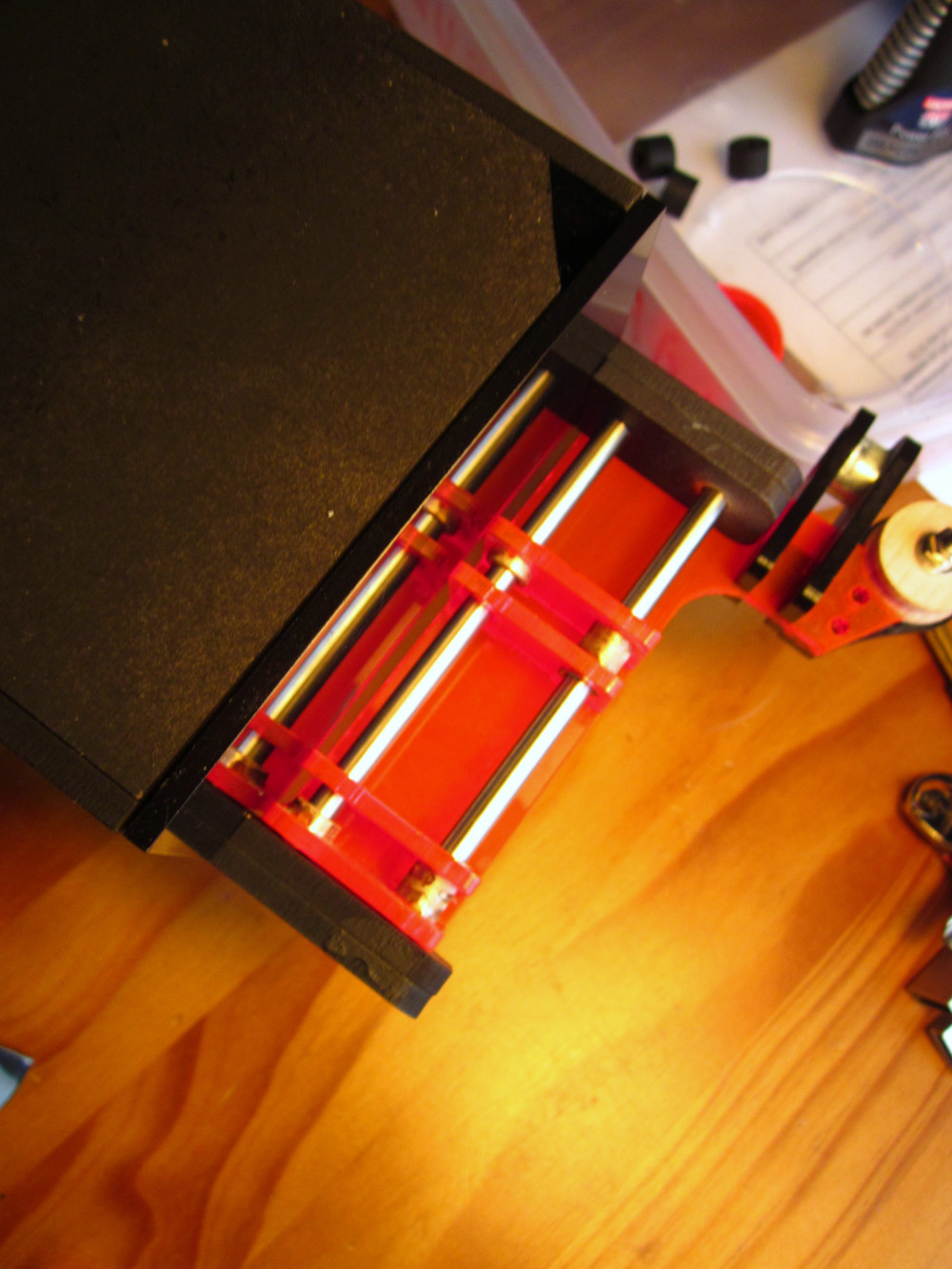
I have seen a few designs online for 3D printed pickup winders, but unfortunately I do not have access to a 3D printer. On the other hand, I do have access to a laser cutter at school. For this reason, most of my projects are designed around flat-packs and this project was no exception. Virtually every part of the pickup winder was laser-cut, including the wire guides and the drive pulleys. This time, I copied existing pickup winder design norms more closely, scrapping the automatic wire guide and the silly spool holder. However I did change one detail: most small hobby pickup winders don’t provide any means to mount the spool, expecting the user to simply put the spool on the floor by their feet. The long distance between the spool and the pickup winder reduces the likelihood of wire snagging or breaking, but to me this system has always seemed a bit inconvenient. I tend to have lots of projects on the go at one time, and I don’t really have dedicated space for a pickup winder, so I wanted a design that I could shove in a draw mid-winding a pickup without having to worry about thin wire getting tangled up. I’m sure this feature is probably considered absurd by any sane person, but hey, I think it looks neat. :)
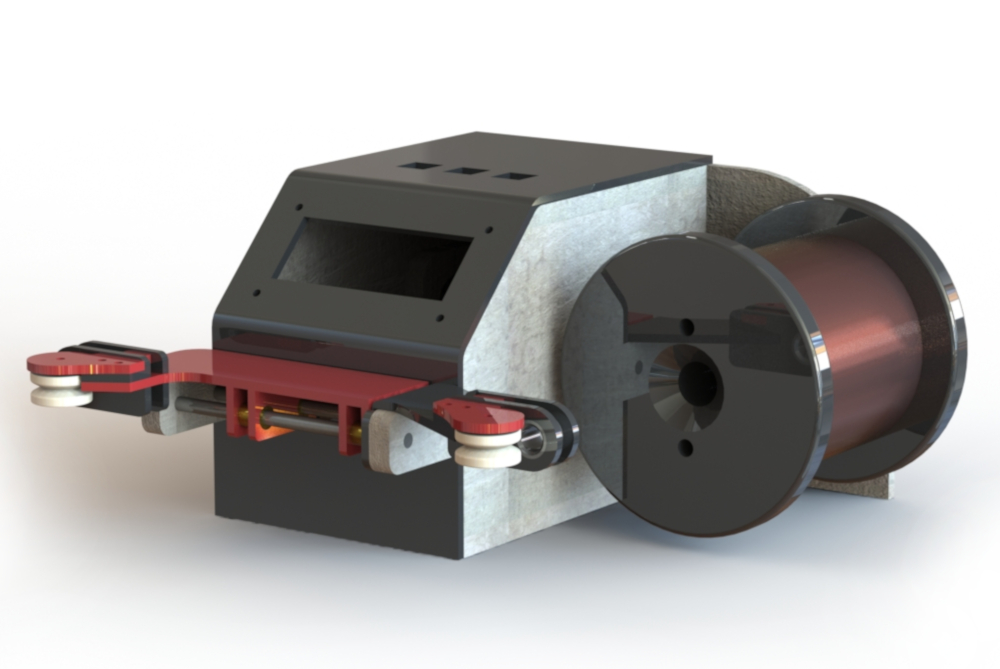
Above is a quick render of the pickup winder drafted in CAD. As you can see, the spool is housed on the opposite side of the winder to the bobbin spindle. This makes the entire unit quite compact, but raises the issue of guiding the wire around two 90° turns, while keeping the wire taut. Moreover, the length of the wire between the pickup and the spool continually varies, as the position of the windings on the bobbin changes. My solution tothe latter of these two problems was to mount the second pulley to linear guides salvaged from a printer. This allows me to guide the position of the windings on the bobbin without touching the wire. The first problem I found harder to tackle. This is because the wire pulls off the spool so easily that the tension in the wire is effectively nill. To avoid sloppy coils and tangled copper wire, the wire needs to be kept taut while winding the pickup. I had planned to do this with a couple of spring-loaded rubber pads providing friction on the infeed, but this didn’t work that well and in the end I left them out and just used my fingers as a brake shoe to keep the wire taut. Other than the tension issue the sliding pulley system actually works quite well.
After a couple of quick tests re-winding some existing pickups, I decided to move onto making my own from scratch. In fact, the main reason I built the pickup winder was to make an especially low-profile pickup for my DIY Electric Guitar Project. As far as I can see, there is still a significant level of voodoo magic involved in making a pickup, particularly surrounding magnet choices. Most of the pros swear by Alnico-5 magnets, but their high price makes them kind of unappealing for my crude hobby attempts. Instead, I tried using the much cheaper ferrite magnets and am very pleased with the results. (I don’t have the kind of equipment required to backup such a statement, nor do I want to engage in an argument about TONE…)
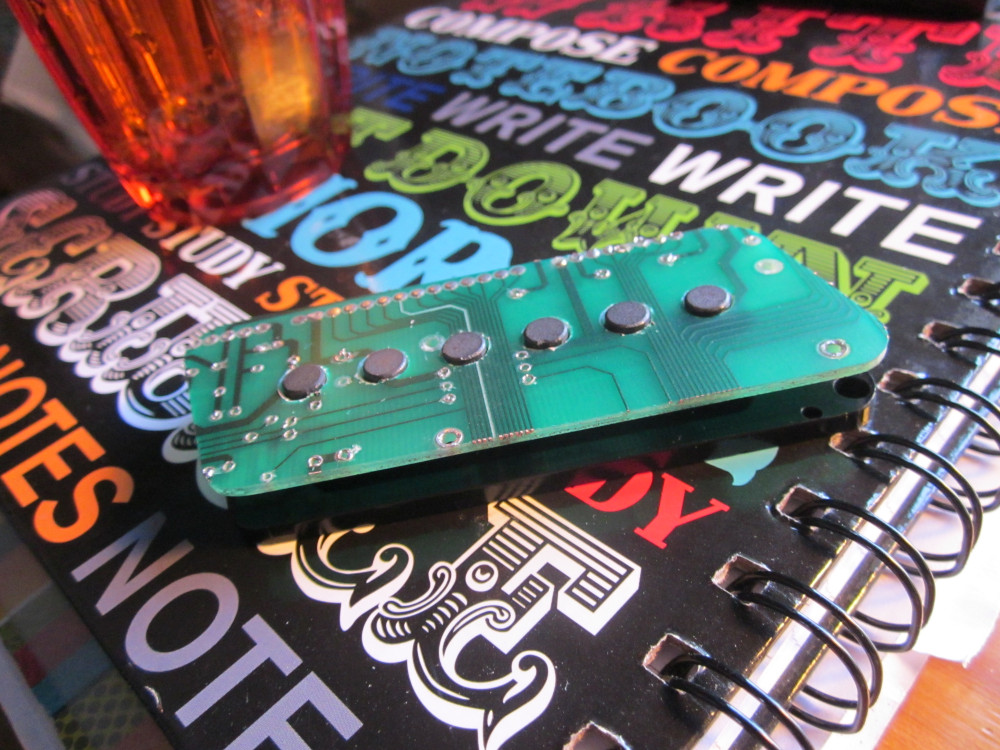
The bobbins of pickups were traditionally made of fibreglass. I didn’t think I had any on hand so had planned to use black acrylic instead, but that would have looked tacky. I suddenly realised that I do have fibreglass sheet at my disposal - in the form of old PCBs! I thought that making the pickup flatwork out of salvaged PCBs would look quite funky. One of the bobbins is pictured below.While this pickup winder has its quirks and annoyances, I find it useful to have around, and building it was quite fun. If I ever start making pickups in larger batches, I may design and build a version 3, but for now, this machine covers my needs just fine.