Touchdesigner: Image -> DMX
31-03-2019
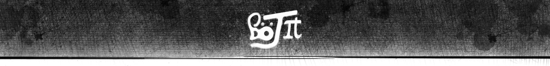
For a recent theatre production I was involved in, I had to do some complex DMX pixel mapping as part of our lighting set. Normally I tackle most lighting programming with a program called MagicQ. The software is free and identical to the software used on professional Chamsys desks, but it does have its limitations. For one, the internal pixel mapping engine (pictured below) is not the greatest. It is usable for simple eye-candy effects with Sunstrips and LED battens, but for anything more exacting than that it is a pain to use. While you can get slightly more functionality by hooking MagicQ up to a media server, but in my opinion, it is better to completely bypass MagicQ and use something else as the pixel mapping engine. In my search for that ‘something else’, I came across Touchdesigner. While it is primarily a video manipulation tool, the sheer number of IO options in the software make it very flexible for all kinds of scripting/automation tasks. For the show I was working on, I used Touchdesigner for more than just pixel-mapping, but in this article I will focus solely on how to create a simple Image->DMX pixel mapper in Touchdesigner. To see what else I did with the software, read this article.
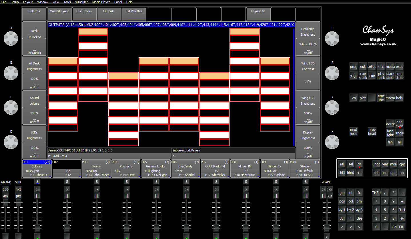
The method outlined here is far from the only way of pixel mapping in Touchdesigner. I have seen some very sophisticated 3D rendering engines and complex node systems for efficient GPU utilisation, and I would highly recommend taking a look at them, but this method is relatively simple to understand and modify, if you are a newbie like me. :) If you are looking for more information on how to make more complex rendering systems, I would encourage you to checkout Matthew Wragan’s website. To make Touchdesigner networks easier to follow, I like to put all operators associated with one task in their own container. Not only does this neaten things up, it also makes it easier to share processing modules with other people as .tox files. Below you can see the inputs and outputs my pixel mapping engine takes: for inputs the container takes a video feed, an intensity slider and a washout/white slider; the outputs are the DMX channels and a preview of the pixel-mapped content. Only one input and output are really required, but having the preview window and the controls broken out makes troubleshooting and mapping controls to MIDI much easier.
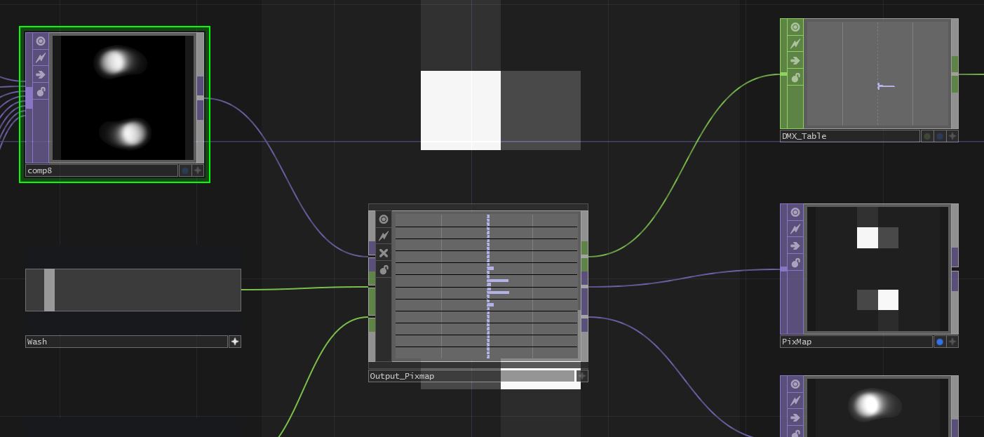
Inside the container, the first group of operators simply handle video pre-processing. The video input is scaled to the aspect ratio of the pixel grid, then is multiplied by the alpha value of a constant colour. The opacity of the constant colour is controlled by the ‘intensity’ slider input. This is a simple way of controlling the ‘brightness’ of the video input without changing the alpha values of the input, which is important later on. A similar operation is done with the addition of a constant colour, controlled by the ‘washout/white’ slider input. This is an equivalent of controlling the ‘tint’ of the image. Any other processing can be done after these operators, but if working with simple dimmers or RGB fixtures, it makes life easier to only apply effects to the RGB channels only and leave the Alpha channel alone.
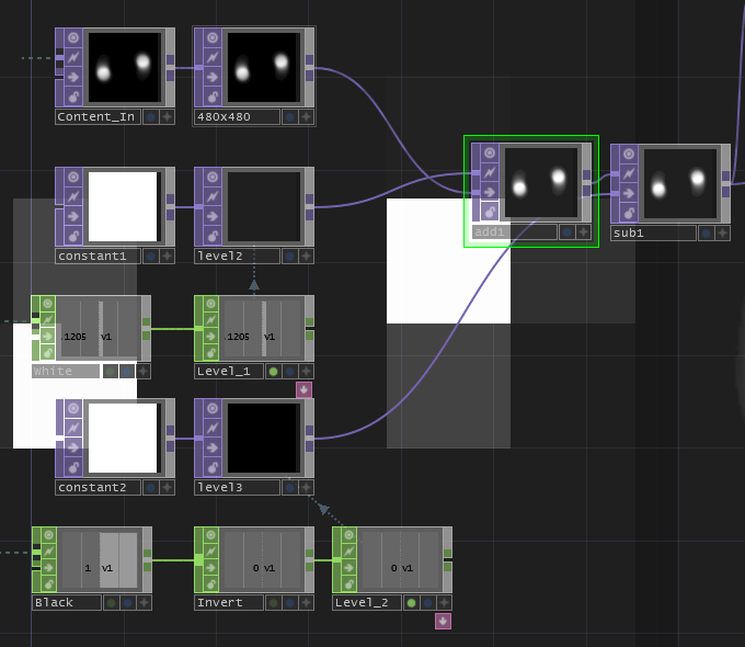
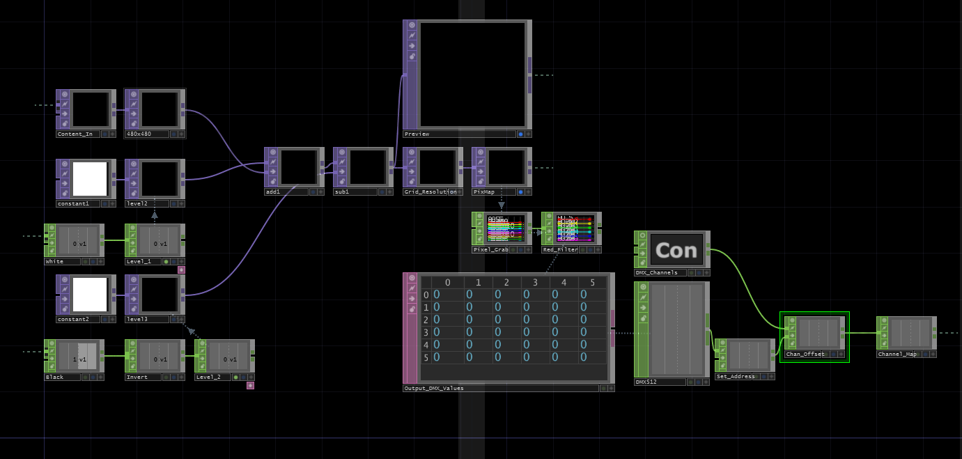
Following this pre-processing, the video is scaled to the desired resolution of the pixel grid, then a TOPto->CHOP operator is used to turn each scan-line of the image into data channel. Following this conversion a Select operator is used to filter all the red channels (using the rwildcard) from the image. If required, this CHOP can be directly manipulated to give the image data in a format that can be output over DMX, however we can deal with the data more intuitively by using a CHOPto->DAT* operator to map every pixel value to a table. This table visually corresponds to the position of elements in the pixel grid, starting from top left and ending in the bottom right-hand corner. Note that for my project my pixel grid was made up of incandescent-style bulbs, so I only cared about the luminance of each pixel in the video feed, meaning it did not matter whether I looked at the R,G or B channel of the data. However if working with RGB fixtures we would need to have 3 separate tables for each colour channel.

Now that we have a nice grid of all our pixel values, we need to turn them into a format that our DMX operator can understand. In my case I was using an Entecc DMX-USB Pro as the physical DMX interface, but the operator also supports output over ArtNet. We need to map our data to a stream of 512 channels with values between 0 and 255. If you are working in 24 bit-per-pixel colour space (8 bits per channel), you probably already have the right range of values per DMX channel, so all we really need to do is map the value of each table cell to one of the 512 output channels. With the image data in DAT form this is relatively straightforward. The first step is to generate 512 empty channels. In Touchdesigner there is a special syntax for doing this with a Constant operator. Simply type chan[1-512] into the first entry of the operator, and you’re done! It is worth noting that while both Touchdesigner and standard DMX work with DMX channels label DMX addresses 1-512, many computer processes and older lighting hardware work with addresses 0-511, so if you experience an ‘out by one’ error when doing fixture addressing, this may be why.
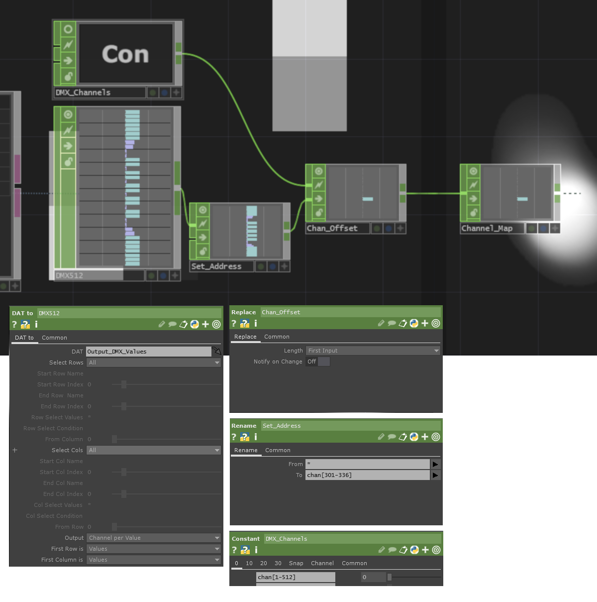
To extract the pixel values in a logical order, we can use the DATto->CHOP operator, using the settings pictured above. This will create channel names that start from 1, up to the number of cells in the table, with the numbers ascending left to right, top to bottom in the table. For monochrome grid systems, this is all the processing required, but for RGB systems all 3 tables must have their channel names multiplied by 3 then offset by a specific amount. This data is in a format that can be fed directly into the DMX operator, but there is one remaining problem. The pixel grid we are using is not necessarily patched at address 1, so the channels need to be offset to the correct address. Note we are not adding an offset to the channel value, but to the channel names themselves. This is done with the Rename and Replace CHOPs. Say we wanted to patch a 6x6 grid starting at address 301, we would use the Rename CHOP to map ’*’ to chan[301-336], then replace the constant channels with our image pixel values in the main channel output. This arrangement is shown above.
This is the part of the pixel engine I am least pleased with, as the start address cannot be set with an external CHOP, and the Rename CHOP does
not adapt to changes in the grid resolution. When I first made this system I was up against a show deadline, so left this annoyance in. If in the future
I design a better system, I will update this page and post the module as a .tox file.
Below is a picture of the the core pixel mapping Touchdesigner network, and I have attached my Touchdesigner file here, in case anyone finds it useful. There are numerous ways to enhance this system, but hopefully the information provided here will be useful if you are doing any projects with similar elements to this. Do check out the project I used this pixel-mapper for, which combines this pixel engine with lots of hanging light-bulbs and an Xbox Kinect!