Greenpower F24 Competition
05-06-2019
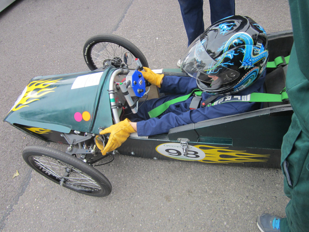
This post is a bit of a hodge-podge mix of projects, as I am trying to cover my activities over the last six years of involvement with the Greenpower F24 Competition. A lot has happened in that time, so the information here is a very small selection of what I have been doing for the competition while I have been involved. Our school’s Greenpower club, Poole Grammar Racing, typically races 2 cars: one is a modified kit car, named Green Dolphin, pictured below. The other was a custom-made carbon fibre vehicle, nicknamed Uncle Bulgaria. This vehicle was very small, and had a few issues with turning circles, but was otherwise the faster of the two cars. By this point you have probably picked up on my use of the past tense with reference to the second car. This is because a student (not naming any names!) managed to write off that car by crashing it into the back of our neighbouring school’s vehicle back in 2015. With that car out of the running, the daunting task of creating a new car loomed…
At the time, I had the most practice with SolidWorks among the members of the club, so I was given the job of designing the new car. Around this point, we also had the opportunity to get composite shells for the new car fabricated by a local composites company called Norco GRP. The CEO of the company is an ex-student of our school, and their generous offer allowed us to explore some new design possibilities. Our plan was to make a monocoque shell, with the only framing being the roll-bars that are required by the regulations. The car was designed to be as lightweight as possible, but slightly bigger than the car it was replacing. Even four years on from when I started working on the car, the CAD modelling was some of the most complex I have done to date. The CAD work from the first draft right through to the initial mould-machining took about a year and a half, in between other projects and commitments. I was learning SolidWorks’ more powerful tools and features as I went along, meaning much of the CAD work had to be re-done with things like in-context dimensions and linked layout sketches, etc… I had to also ensure that the shell designs were conducive to the composite moulding process, and all of the mechanical parts could be machined in a school workshop. To round this off, I was doing all of this CAD modelling on my old 2011 ThinkPad, which was way too underpowered for this task, and would crash SolidWorks every half-hour or so!
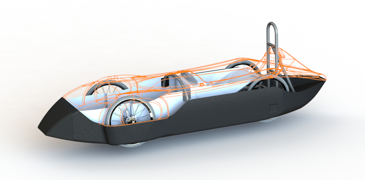
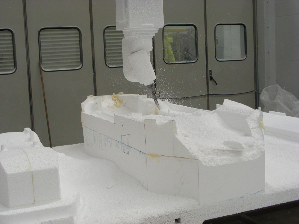
The result of all this work is illustrated above. The design is primarily made up of 3 composite shells: the main bodywork, which contains all of the important fixings and mounts the roll-bars; the inner tub, which mounts the front wheels and holds the driver; and the top yolk, which has nothing mounted on it and can be quickly removed for access and maintenance. In an effort to mimic some of the more successful car designs in the competition, we designed the car with all four wheels enclosed to reduce drag on the vehicle. The other important aspect of the design is that the moulding is relatively simple geometry. The top yolk, internal tub and dashboard assemblies can all be built up on one-piece moulds; the main body unfortunately is a bit more complex, with 3 independent mould sections that assemble together. We worked very closely with Norco and its sister company MouldCAM to ensure that our design was suitable for manufacture from the very beginning. Below is a picture of the initial CNC machining of the moulds on MouldCAM’s 5-axis behemoth.
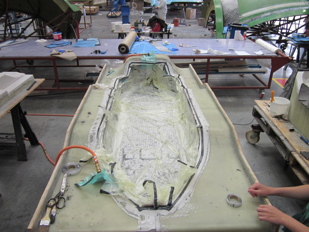
Our shells were made with a process called vacuum-infusion. This essentially consists of laying the composite down in the mould on top of a release agent, then coating the material with epoxy. Then, a variety of porous, non-porous and absorbent sheets are layed down on top of the mould and sealed around the edge with rubber tape. The bag is hooked up to an industrial vacuum and the bag ‘pushes’ the composite tight to the mould forcing the excess epoxy into the absorbent sheeting (see picture below). This method is much cheaper and simpler than using prepreg or an autoclave, but can be quite risky if the vacuum seal is not perfect. We had a mysterious leak in the first mould during the lay-up, and we were up against the clock to find it and plug it before the epoxy began to set. In the spirit of Greenpower, we decided to lay up our composite using 2 layers of carbon fibre, with a layer of ‘flax’ in between. This material is similar to that of a hessian sack and has the advantage that the offcuts from the manufacturing process are biodegradable. It also gives the shells a bit more flex, making them less likely to shatter on impact. What we hadn’t accounted for was quite how much epoxy the flax absorbed, meaning our dry-time calculations were off by a considerable margin!
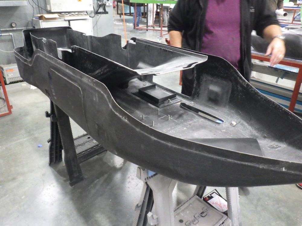
Aside from these minor complications, the lay-up process was relatively straightforward. A week after finishing the layup, we were back at Norco ready to pop our car shells out of the moulds. However before doing so we had one more issue to address… Fastening to composite is not always straightforward and we had experienced many problems with the old car where bolts and fixings would tear out of the composite. Many of the joints on the previous car had simply been done with a hole through bare composite and a pair of large washers on either side, making them much weaker than a professional composite fixing. Determined no to face these issues again, we planned the location of all the possible fastenings and embedded either aluminium plates or Bigheads into the composite at various index locations we had scribed into the moulds. The final task was to bond the surface fasteners and lay composite over the top of the larger plates. This meant we were never mounting fixings directly to the composite itself, reducing the likelihood of bolt tear-out. Below is a picture of the bottom and inner tub after they were removed from the mould and trimmed. Below that is a little promotional video that Norco made for the website. Apologies in advance for the terrible voice-over I had to do for the video: I usually make an active effort to avoid cameras, so being forced in front of one is bad news for everyone involved!
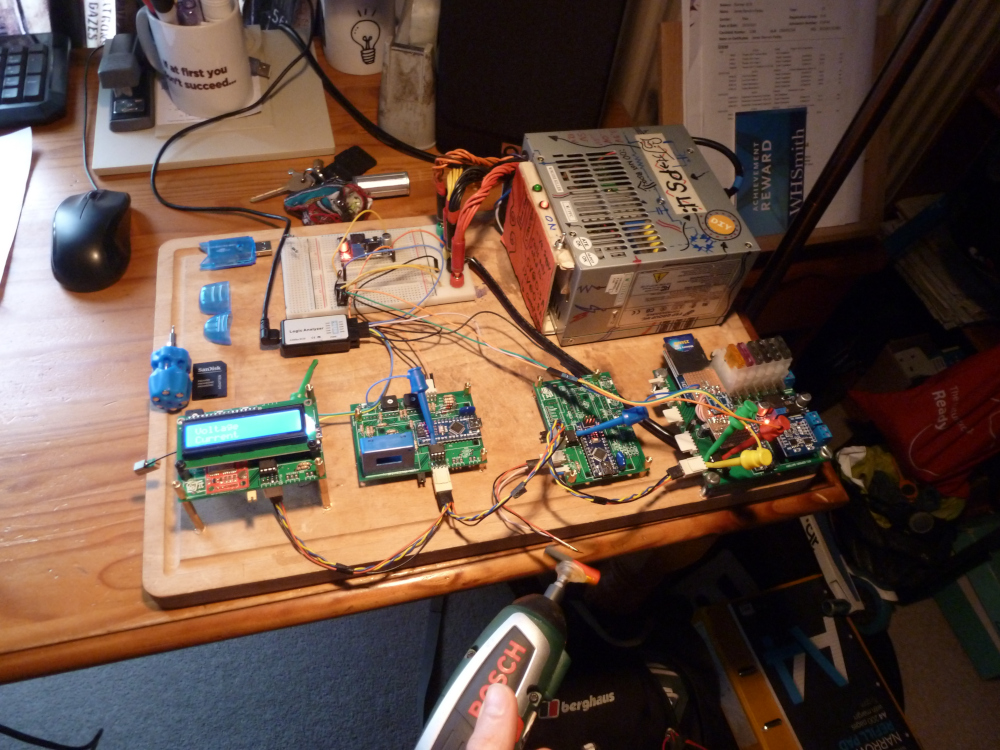
Since completely finishing the shells, we have slowly been working on the rest of the framing and drive mechanisms. This has been taking longer than expected, in part due to regulation changes during manufacture of the new car. One such setback was the regulation change stipulating that all roll-bars must be made from steel tubing. By the time the regulation was announced, we had already welded up all the framing in aluminium! This is not the sole reason for delay, however. The usual issues of lack of team willingness, time constraints and management bureaucracy also have taken their toll. With only a year left in school, I decided to turn my attention towards the car’s electronics and data-logging system, as this was a task manageable enough in size that I could tackle the bulk of it on my own. I won’t go into extensive detail here, as the system is overly complex and still under development, but the core arrangement of the system is a master board, with a series of slave boards that receive instructions and relay data over a half-duplex RS-485 bus. The system regularly logs voltage, current, temperature, RPM and GPS co-ordinates to an SD card, then displays selected data on an LCD screen. I have included a picture of the fully working prototype below, and all of the code and schematics are up on GitHub if anyone is interested.
I have loved working on the Greenpower cars and have learnt countless skills while doing it, however after six years of hard and at some times frustrating work, I am glad that my involvement with the project is over…for now…