DIY E-Drums
16-05-2020
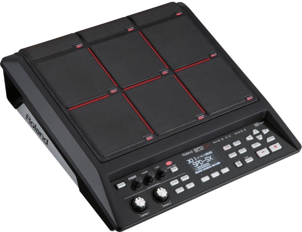
For a while I have window shopping for a drum sampling pad - in particular the ubiquitous Roland SPD SX (see picture below). However for the light use I will likely get out of a pad set, I can’t really justify the high price for a proper set. So instead, I thought I’d try to make my own! These DIY drums don’t have any form of sampling capabilities or sound-generation: they only output MIDI. This doesn’t bother me, as all of my drum rack samples are generated in Ableton, however if you wanted to add inbuilt sampling/sound generation there are many Raspberry Pi based projects designed for this task. This one is relatively straightforward to build and interface with a MIDI input.
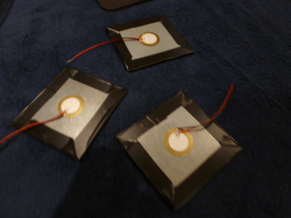
The first and probably most crucial step of the E-Drum creation is to make the piezo pads themselves. There is a wealth of information on the subject online, however most of the similar builds that I found had the pads completely separate from one another. For an SPD SX-style design with all the pads mounted on the same surface in close proximity to one another, crosstalk becomes a major concern. Diagnosing crosstalk through serial and MIDI messages is fairly tiresome, but thankfully I now have an oscilloscope! Below is a picture of me testing a commercial pad (origin unknown) against my homemade pads. Interestingly enough the Piezos behave quite differently when struck with Hot Rods compared to regular wooden sticks.
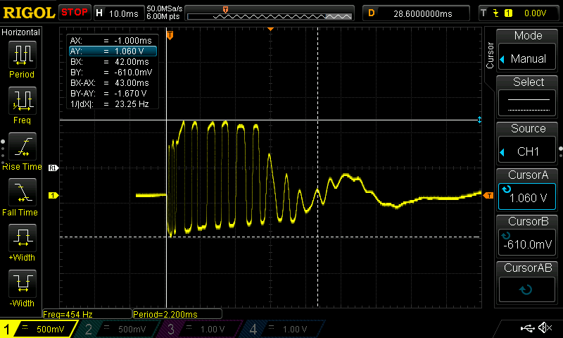
The input that the STM32 ‘sees’ looks something like the oscilloscope capture shown below: Note that my hardware does not have any input filtering, only a 1MΩ resistor and a reverse-biased 3.3V zener diode across the output of each Piezo. The resistor helps clamp down the noise on the analogue input when the piezo is not struck , while the zener diode simply stops the voltage on the analog input straying outside -0.7V -> 3.3V, protecting the microcontroller hardware. The lack of any filtering means two things:
- We need to sample the input at a frequency that is an order of magnitude higher than the resonant freqency of the pads (this avoids missing the samples or recording inaccurate velocities).
- The peak detection has to be done in software, without misidentifying retriggers or ‘ghost notes’.
The algorithm I used for processing the signal is very simple, and has plenty of room for optimisation, but it works surprisingly well. If you are interested in a superior hardware approach to processing the piezo signals, I would recommend reading this article.
The algorithm loops through each input, reading the analogue value to a variable called sample. Each input has 5 global variables (stored in an array):
PAD_NOTES[10]- contains each input’s MIDI note value.PAD_PINS[10]- contains the pin macro mapping the input to the physical pin that has to be read.PAD_ACTIVE[10]- a boolean representing whether the input is ‘ACTIVE’ or not: (triggered when threshold is exceeded).PAD_SAMPLE_[10]- a buffer of the previoussamplevalue for each input.PAD_HOLDOFF[10]- a timestamp (frommillis()) indicating when the input becomes ‘ACTIVE’.
The processing is split into two stages: the first stage is to check when the input exceeds a certain ‘Threshold’. This threshold is globally defined and is set slightly higher than the noise floor of the piezos and any light crosstalk. Once a particular input exceeds this threshold, it is marked as ‘ACTIVE’, and the PAD_HOLDOFF[i] is set as the current timestamp [see code snippet below]. However, the pad can’t be set high unless a certain ‘Holdoff’ period has elapsed. This is a global variable that defines the minimum time between two consecutive triggers. It should be set short enough to allow for fast drum rolls, but long enough to prevent the trigger ‘bouncing’.
if((sample > PAD_SAMPLE[i]) && (sample > THRESHOLD) &&
                            (time - PAD_HOLDOFF[i] > HOLDOFF)) {
  PAD_ACTIVE[i] = true;
  PAD_HOLDOFF[i] = millis();
}
Once the channel has been marked as active, we can’t immediately send the MIDI note, as the sample that is measured when an input exceeds the ‘Threshold’ does not give us any real knowledge of the velocity of the drum strike. There are a multitude of methods of processing the input signal to derive a velocity, but the one I like the best is to wait until the most recent input sample is less than the previous sample (i.e. the first local peak has been reached). We then work out the velocity by multiplying the 12-bit anologue input value by 127 and divide through by the ‘working range’ of the ADC (2^12 - Threshold). This method doesn’t work that well for really soft notes, but it doesn’t involve any averaging or arbitrary delays, so the pads feel really responsive! The fact that the code in its entirety is not much more than these two snippets makes it quite easy to make a drum set with lots of pads and very low latency.
if((PAD_ACTIVE[i] == true) & (sample < PAD_SAMPLE[i])) {
  int velocity = (sample - HOLDOFF)*127/(4095 - HOLDOFF);
  MIDI.sendNoteOn(1, PAD_NOTES[i], velocity);
  PAD_ACTIVE[i] = false;
  MIDI.sendNoteOff(1, PAD_NOTES[i], 0);
}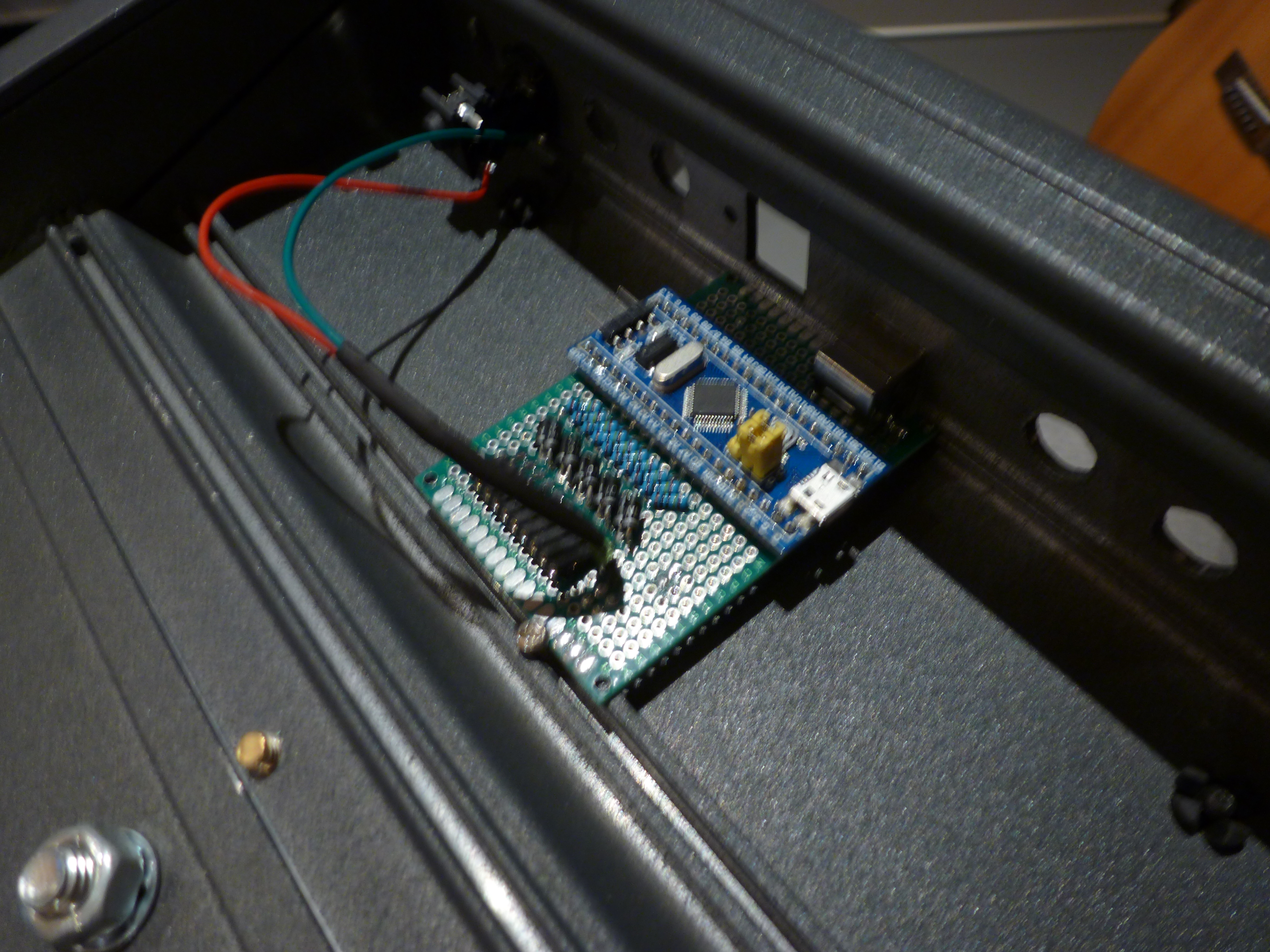
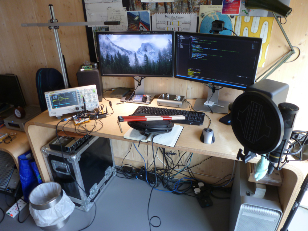
The hardware (pictured above) is equally minimal. I was considering adding some LEDs and buttons to the unit, but considering it will never be more than 2 metres from my computer I decided against it. The drums have no onboard controls - everything is done over MIDI.
The casing is actually a cut-down section of an old Strand LX analogue lighting console I managed to scavenge from a school clear-out. It is already shaped a bit like an SPD SX, and it is almost indestructible! It also has 1.6mm grooves built into the extrusion, so mounting my perfboard controller inside was a breeze. I added an extra serial header that outputs serial MIDI, in case I want to add a raspberry Pi as an onboard sound module at some point in the future.
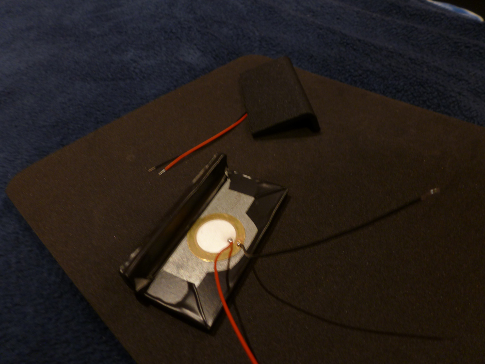
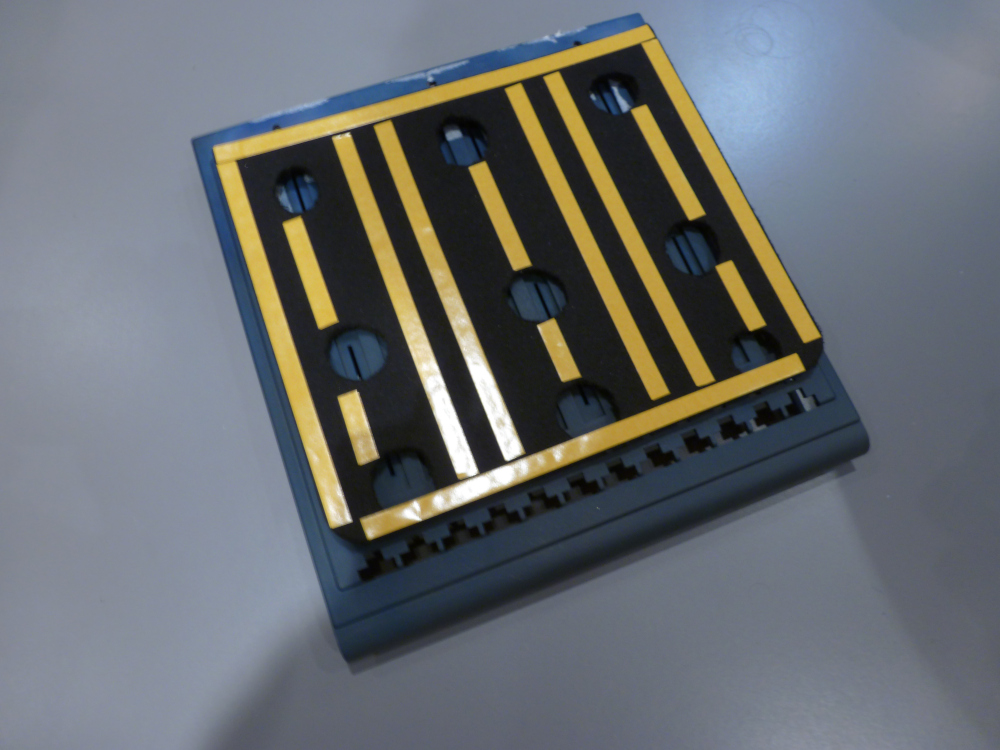
The pads are constructed from some scrap angle iron which have rubber/fabric mouse mats epoxied onto the top surface. The thicker-than-ideal metal makes the pads feel a bit less like a drum that I would have liked, but it makes the pads respond very consistently regardless of where you strike them with the stick. The piezo elements are just lightly epoxied onto the back of the metal, and the edges are sealed with electrical tape.
After some quick testing with the scope, I confirmed that the pads did respond reasonably similarly to the commercial pad that I was using for the kick drum, but even having the bare pads just resting on the same surface would result in horrendous crosstalk between the pads. To try and prevent this from being a problem in the finished article, I used a much thicker foam mouse mat with sections removed to create floating supports for the pads. In retrospect I should have probably used softer foam, as crosstalk is still an issue, but the foam mount isolates the pads enough from one another to make the kit quite playable.
Below is a quick video of the finished pads in action. I use both Hot Rods and regular sticks, and the difference is quite noticeable. The Hot Rods result in far less cross-talk, but it is hard to play quickly without some notes being dropped. In contrast, the regular sticks trigger much more relaibly, but I have to be quite careful to avoid neighbouring pads being triggered accidentally when playing!
These pads are by no means a substitute for a real SPD SX, but for a hobbyist like me, they are great fun and can be built at a fraction of the price of the real deal!