Portable CNC Machine
03-05-2019
Before you start reading this article, you should probably know two things…
Firstly, I never finished this project. I plan to come back and revisit it once I have access to the right tools again, but for now you should consider this as more of a concept project, one that taught me a lot about how to build things and how to design parts that aren’t a nightmare to make.
Secondly, considering that I spent nearly two years working on this thing, I have virtually no photos of it! I built this back in the day where I still used a compact camera for all my pictures, storing the images across a disorganised mess of SD cards and USB sticks. As I am writing this article five years later while living on the other side of the world, I am unsurprisingly unable to locate that SD card. Maybe some day I’ll find it at the bottom of a dusty drawer and add some more pictures to this page. But for now, you’ll just have to rely on my descriptions!.
Context
I’ve always wanted a CNC machine. For the things I generally make, it is a far more useful tool than a 3D printer, and for a (at the time) student with no real space for a workshop, it seemed like the ideal “one tool” that would let me make virtually anything!
The trouble is that CNC machines are big, bulky and very messy. In order to get a good cutting experience, the frames have to be very rigid to dampen vibrations. What this usually means is that they are very heavy.
What this means in practice is that most CNC machines are designed to be placed in one spot and seldom moved. Many designs bolt into the floor, and even the free-standing ones can’t be easily moved without some serious effort.
What I wanted to make was a machine that was both portable and still rigid enough that I could do some reasonable heavy machining. Certainly not a machine capable of cutting steel, but something that could at least deal with hardwoods and maybe the occasional bit of aluminium.
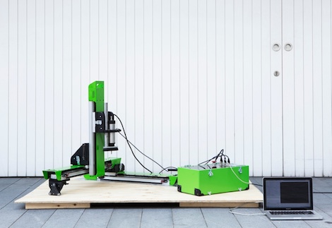
A similar project existed at the time: a design museum piece called the Grow CNC (see image below). The design seemed like a neat idea, but the design seems to have the following limitations:
Each axis is a cantilever supported at only one end. This is good for making the design easily disassemble-able, but makes the machine very sensitive to deflection while cutting. You can see a fair bit of chatter during cutting in their promotional video.
The Z axis clearance is very small, making the machine mostly suitable for low height workpieces (strangely enough the axis is very long despite the fact that the tool stick out does not clear the gantry for most of the travel!)
It uses a follower wheel as the axis reference on one edge. This means that the accuracy of your parts is very much subject to the flatness of the surface you set up on.
All in all it seems like a solid design, but is limited to cutting sheet materials with a relatively low accuracy. This isn’t really the kind of work that I do, so I looked for alternative ways of creating a disassemble-able axis system which provides more resistance against deflection.
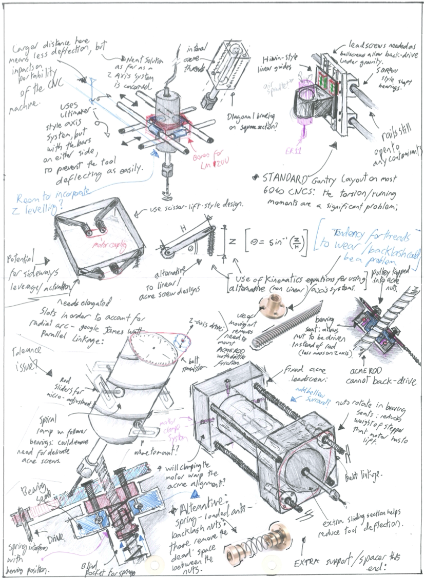
As I was doing this for my A-Level design coursework, I did a bit more sketching than I would normally do for a project like this. A snippet of my portfolio is shown below. The key thing I was trying to do was create an axis system that kept the spindle rigid in torsion. Normally this is done by making the moving axis very rigid and using linear rails to mount the Z axis to the gantry. However, this design tends to end up being very bulky and heavy. Instead, I looked to try and use a “Cross-Gantry” design where the Z-axis is at the intersection of an X and Y axis. This way, the gantry can be much less substantial, as its twisting motion is resisted by the other gantry that is perpendicular to it.
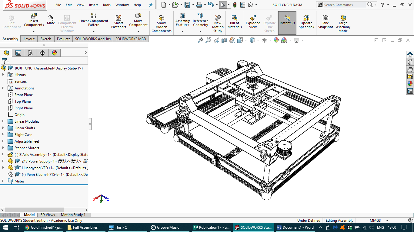
You can see this scheme more clearly in my machine CAD. The gantry provides very good stiffness against lateral forces applied to the end of the cutting tool. The downside of these designs is that you typically have to drive both sides of the gantry, or else the mechanism is liable to “bind” when driving the gantry from a single side.
Note that this means that both sides of the machine have to be kept in synchronised position. If the stepper motors get out of sync, the machine may end up stalling or pushing the gantry ever so slightly out of square. This can be challenging, but thankfully for this project I already had a closed-loop stepper driver design in the works!
You can see in the CAD that each gantry “axis” is an independent piece that can be snapped together. The gantry rails are just 12mm stainless rod that is snapped into the axes pairs before the two halves are connected.
Another key thing I wanted to get right on this machine was a good swarf/chip management scheme. I already knew that my machine wasn’t going to have an active mist/flood coolant system, but I wanted to have the option of using air/hand-applied cutting oil if the need arose. Many of the cheaper “X-carve”-style machines simply use the bare slotted extrusion as their linear travel axes. These extrusions tend to fill up with chips and affect the machine’s operation if they are not kept clean. For my design I wanted to have all of the linear drive components kept hidden within a sealed channel behind rubber bellows.
The base of the machine is actually made out of the case that the box comes in. We’ll come to that later!
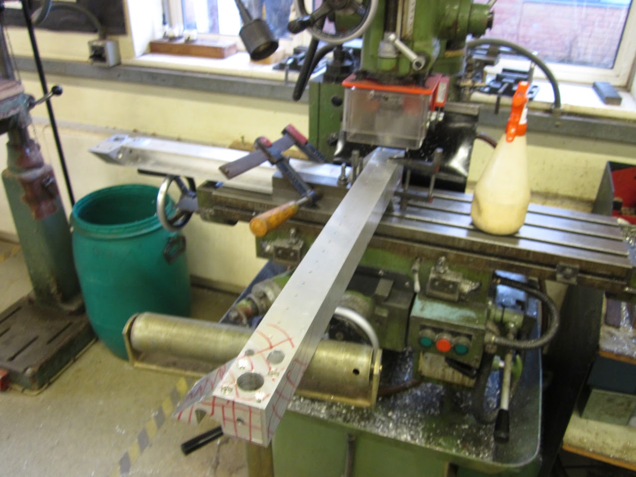
In order to make the machine so rigid and compact, I had to resort to using a lot of bespoke part designs. When designing the CNC, I came to realise exactly why having a CNC machine is so useful! The process of machining all the parts on a manual mill took months! What’s more, at the time I had a very limited understanding of GD&T, so many of the parts I’d designed relied on getting multiple press-fit locating pins to line up between different parts. After quickly realising that my machining skills were not up to the task, I resorted instead to machining a lot of the matching parts in one setup, which led to some quite chaotic mill setups! (see below).
The other key mistake I made was relying on standard un-machined extrusions in order to make my linear axis components. I designed the entire machine around cold-rolled aluminum C-section, which would form the base surface that each linear rail would be attached to. The problem is that this extrusion tends to have a fairly relaxed tolerance to bows and twists along the part’s length. The parts I made had up to 0.5mm flatness deviation across their length, so I had to get very creative with shims and adjustment bolts!
One of the challenges with ‘portable’ CNC designs like this is ensuring that they retain their calibration between assembly and disassembly cycles. For my machine I took the neanderthal approach of making none of the axis joints adjustable, instead designing them to be way more stiff than necessary and ensuring that any key tolerance between mating parts was set when I machined the parts.
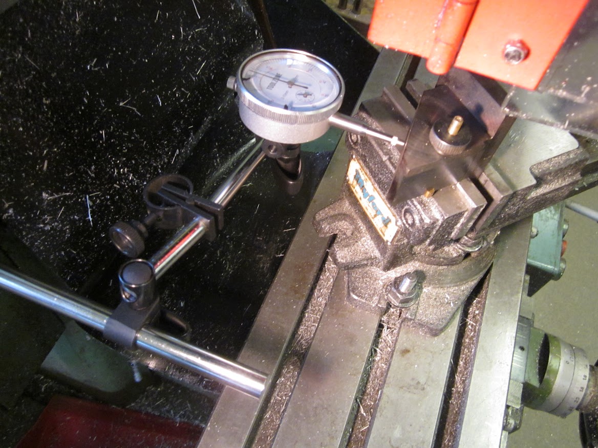
In practice, this meant lots of tedious setups on the mill sweeping a dial indicator across the full length of a machine axis even when I was only machining small parts. This approach did work, and the axes are always perfectly perpendicular when the machine is assembled, but it did have the unfortunate consequence of tripling the manufacturing time!
I was very lucky that when I was building this machine, I had access to a very sturdy old Myford milling machine. I don’t think that this project would have been possible without access to heavy-duty milling equipment that my school would let me use perhaps more freely than they should have! I learnt a hell of a lot about what kind of features form a challenge when building things, a skill that comes in handy a lot in my day job now!
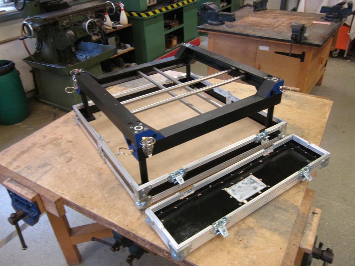
Now onto the more fun bit of the build: the enclosure! Since dreaming up this project I’d had the idea that I wanted the machine’s box to become the work surface that you could use for clamping and work-holding. Some kind of flat pin-board that I could attach cam clamps to (check out Marius Hornberger’s design, or my Router Sled if you haven’t already seen them). I also wanted to make the case out of that nice shiny flight-case hardware. Partially so that I could shove the machine into a car without worrying about it, but mostly because I like the Aesthetic!
The scheme I came up with was a rather unorthodox 3-part flight-case, made up of one lengthwise spilt and one horizontal split. The idea is that all of the electronics/VFD lives on the top cap, then the two larger sections fold flat around a central pivot hinge to become the machine’s base. Doing this meant designing a strange scheme where the lid extrusion has to flip orientation mid-way on some box edges.
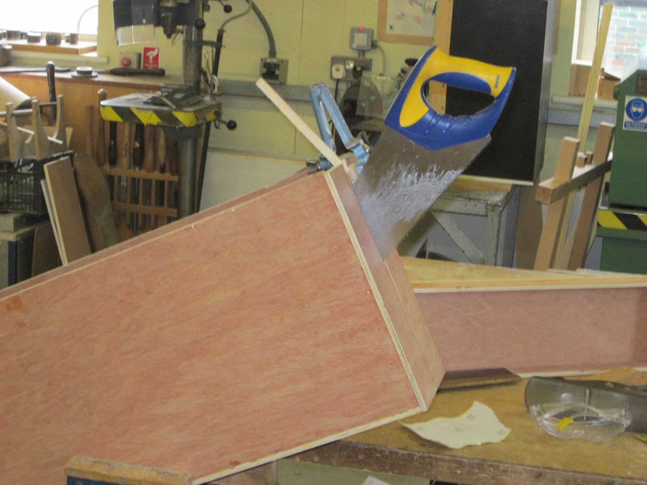
Getting all of the box segments to line up perfectly was going to be hard, so instead I decided to build a completely sealed box, then cut it into sections “houdini”-style!
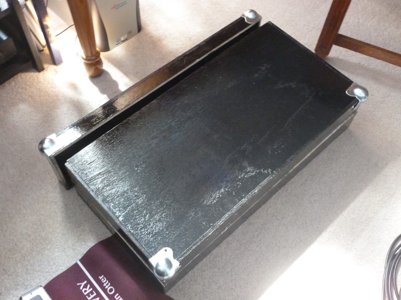
Installing all of the flight-case fittings is very straightforward assuming you have a pop riveter. Once the box had a lick of paint and some silver hardware it started to look quite sharp!
Fast-forward a couple of months, and I had all of the key parts machined, the box made, and put on a couple of coats of paint. It was about at this point that I had to prepare my A-Level coursework submission, so things halted for a little while, but the machine was complete enough for me to make some key realisations:
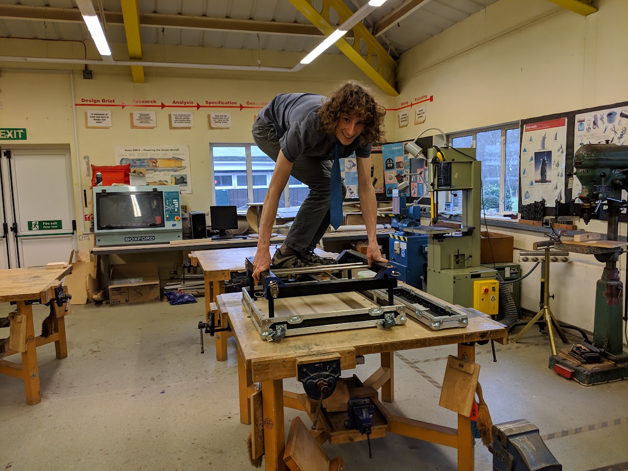
The machine’s gantry is plenty rigid! I had definitely been a bit too cautious when beefing up all of the gantry parts. As you can see from the bottom picture, I can easily jump up and down on the gantry and see less than 0.5mm deflection at the tool head area.
When packed up, the casing weighs an absolute tonne! I’d probably tried to be a bit greedy when CADding the machine to ensure that absolutely every bit of space was used when the machine was disassembled. As a result, The box is probably about 70% steel and aluminium by volume! Even on wheels, this thing is awkward to lug around.
I tried to make all the axis assemblies identical. While this is good practice for BOM/assembly time reduction, it’s not necessarily a good idea for a calibrated machine. While I can put the machine together in multiple configurations, there’s only one configuration where the axes are all fully aligned to one another. If I were re-designing it, I’d ensure that each part can only assemble in one single configuration.
Now, to get this machine finished I still need to machine some Z-axis parts. And unfortunately since leaving school I haven’t had access to a large enough milling machine that I can use for long enough periods of time to finish making the machine…
… which brings me to the sad conclusion of this article. I wanted to build a very capable portable CNC machine to avoid the need to have an extensive workshop. But to build a very capable CNC machine, it really helps to have an extensive workshop!
So for now I think I’m going to leave this machine as an interesting design experiment. I may either finish it or design a Mk.2 at some point in the future, but at that point I’m likely to have a big enough workshop space that I don’t need to make the machine portable any more!
